Sometimes you have to use an Arduino UNO, instead of something more efficient like an Arduino Pro Mini — maybe you’re using an Arduino shield…
Sometimes you have to run that same project from battery power, and every milliAmp counts…
Sometimes that means that you’ll have to adjust the UNO to be much more power efficient, so you pick up a sharp scalpel, bring over the big loupe, and warm up the fine tipped soldering iron…
The post formed part of development work performed for the Environment Agency. It has been re-published here with their kind permission, as part of the project commitment to open source development.
The Arduino UNO is designed as a development board, instead of a specific low power device, it is built with several design choices that mean it uses more power that the minimum necessary.
TL;DR: To reduce the overall power usage of the Arduino UNO board significantly:
- replace the linear regulator with a DC-DC converter,
- adjust the USB-to-Serial circuit so it’s only powered from the USB port,
- cut out (or desolder) the always-on LED’s on the board,
- use the processor sleep mode.
Using on-board circuit changes, selective replacement of components and the use of microcontroller sleep mode can reduce the continuous idle power usage of an Arduino UNO to only 5% of the default draw.
Experimental Set Up
Current measurements were made using the blink sketch that forms part of the standard Arduino Optiboot bootloader. This ensures the results are comparable across any board, and may be tested on other controllers using the default sketch. Additionally, a blink sketch is available in the examples provided with the Arduino IDE, and can be loaded on to a board without any additional software libraries.
Current measurements were all made the same way, with the same equipment. A “µCurrent Gold” was inserted between the 12V supply and the DC jack on the Arduino UNO on the 12V line. The same DC supply was used for all tests, a PowerPax SW4298D 12V, 2A mains to DC supply.
The µCurrent Gold is a precision current adaptor converts the current measurement across a sense resistor and amplifies the voltage to provide very accurate measurements (±0.1%) with very low voltage drop on the input (20µV/mA) to minimise the supply change. The output signal is 1mV/mA, so it can be read manually as milliAmps with a multimeter on the milliVolts range.
Initial readings were taken over several cycles and averaged to give a single value, and values are given for both the built-in LED off and LED on condition during the LED blink sketch.
| State | LED off | LED on |
|---|---|---|
| Base UNO | 53mA | 55mA |
Table 1: Base Arduino Uno current measurement.
Voltage Regulator
The biggest power loss in the standard Arduino UNO board is from the voltage regulator that limits the input voltage to the DC input jack. The board uses a linear regulator, which dissipates any supply voltage above the target voltage as heat. With a 12V input, and a 5V output, around 58% of the input energy is lost, either dissipated as heat, or used for the internal supply of the regulator.
Changing the regulator for a more efficient “buck” converter will reduce the power losses — as DC-DC step-down converters can be as high as 92% efficient, depending on the specific usage.
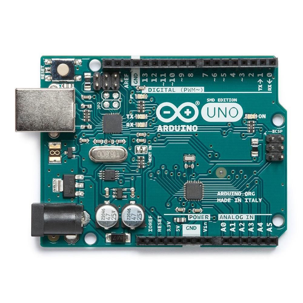
Unfortunately there is no pin-equivalent buck converter that matches the SOT-223 footprint of the NCP1117 linear regulator used on the board; particularly as it has a non-standard regulator pin assignment (1. Ground, 2. Output, 3. Input). However a leaded DC-DC converter can be made to fit the available footprint.
The default NCP1117ST50T3G 5V 1A linear voltage regulator
The Traco TSRN-1-2450 is a 5V switching regulator with built in capacitors. As a pin compatible replacement, it can be used in place of 78xx series linear regulators with out requiring any external components. Efficiency of the switching regulator is up from the linear, with a typical 83% transmission of power, although this depends on supply voltage.

Bend the legs to match the pad position
Clip the NCP1117 and unsolder the remainder from the pads
Although the Traco TSRN-1 is not a pin compatible replacement, by bending the legs, it can be placed on and soldered to the surface mount pads where the NCP1117 has been removed from.

The Traco TSRN-1 switching regulator soldered in place
Changing the regulator reduces the current usage of the board by 48%. Although this reduction may vary, as the efficiency of the regulator varies, depending on the current demands of any driven circuit.
| State | LED off | LED on |
|---|---|---|
| Base UNO | 53mA | 55mA |
| Traco DC-DC | 27.5mA | 28.5mA |
Table 2: Replacing the linear regulator.
USB to Serial converter
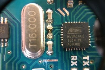
In addition to the main ATmega328 microcontroller on the Arduino UNO board, there is also a USB-to-Serial converter chip, the ATmega16U2. This is a general purpose microcontroller with on-board USB capability that is programmed to act in this job.
Although the chip is suitable for use as a USB-to-Serial (UART) converter, no power saving measures are implemented on the chip, meaning that it remains in a full power idle when not being used. If the chip could be automatically powered down when not in use, this could significantly reduce the idle current draw of the whole board.
We decided not to investigate if the chip can be put into a low power mode via the firmware as updating the firmware on this chip requires a separate ISCP programmer and would not be as simple as uploading a new program to the main microcontroller via the Arduino IDE. Instead only hardware changes were investigated; though the restriction of maintaining functionality is required.
Like the main microcontroller, the UART chip is powered from the regulated 5V line, so it is powered from the USB line when only USB power is supplied, and is powered from the regulated DC input when present. A comparator and MOSFET perfect diode switch ensure only one source is selected.
From the Arduino UNO schematic, the ATmega16U2 (U3 on the board) is powered through pins 32 & 4 from the rectified 5V line. As this line is physically close to the USBVCC bus, the tracks on the PCB to pins 32 and 4 can be cut, and reconnected to USBVCC so the chip is only powered when voltage is present on the USB connection. Athough this is not a recommended power connection for the chip, as the USB supply voltage must be 5V ±0.2V, there should not be enough difference between the supply and any signal voltages to damage the chip.
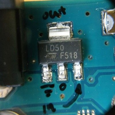
First cut the 5V supply on the bottom of the board that supplies 5V to the 16U2 (to pin 32). This chip is a in a 32 pin package, where the pins are numbered anti-clockwise from the top left corner — indicated by a dot on the top of the package. The cut is made on a trace on the reverse, so the capacitor between pin 32 and ground is not separated from pin 32.

Reveal the 5V supply for pin 32 without compromising C7

Cut across the trace and remove the centre material
Pin 4 also needs to be separated from the 5V line, and can be done on the top layer of the board. At the same time, the track from pin 32 should be exposed along with an area of the track connected to pin 31, so pin 4 & 32 can be connected to the USBVCC line of pin 31.
Expose the traces on pins 4, 31 & 32
Cut the trace from pin 4 without disconnecting the local capacitor
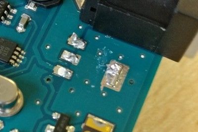
Pin 4 & 32 can be connected back to pin 31 with a single jumper wire. By using 30AWG “wire wrap” solid core wire, cut to 13mm long with 2mm stripped back on each end and turned at 90 degrees in plane, the three connections can be made with one jumper wire.
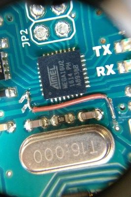
A 13mm long jumper wire with the ends stripped back by 2mm each connects the supply voltage to the USB supply only
Please note that just changing the supply source is not sufficient to completely remove the power usage from the chip. Because the RX and TX LEDs are connected to 5V and sink power through the ATmega16U2 when lit, removing power from the microcontroller means they will always be lit. The only choices then are to cut the traces to the LEDs or desolder them, so they cannot be used.

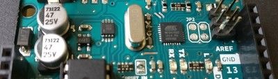
Cut the RX and TX LED traces at the anode to prevent them sinking current through the unpowered ATmega16U2
Changing the board so the UART converter is only powered from the USB connection — and therefore only uses power when the programming connection is made — reduces the power usage by 44.7%. This change does not affect the programming of the board; when a computer is connected by USB, the chip is powered by the computer only, and the main ATmega328 can be programmed by the Arduino IDE as normal (although resetting the board can now cause the USB port to be renumbered by a connected computer).
| State | LED off | LED on |
|---|---|---|
| Base UNO | 53mA | 55mA |
| USB power the UART | 29.2mA | 31.5mA |
Table 3: Remove power to the ATmega16U2 UART converter.
Power LED
As the Arduino UNO is designed to be a development board, it has a continuous indicator that the board is powered using an always on LED. For low power usage, this continuous current drain is not required, but the LED can only be disabled by cutting a track on the PCB, or desoldering it from the board.
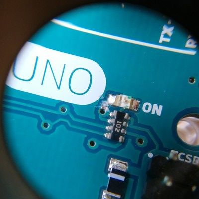
Cut the track between the power indicator LED and the inline resistors
| State | LED off | LED on |
|---|---|---|
| Base UNO | 53mA | 55mA |
| Disconnect LED | 46mA | 48mA |
Table 4: Disconnect the power indicator LED to lower current by 7mA.
Combined
For the voltage regulator change, this is a largely geometric change, as the overall efficiency of voltage conversion is increased, although note that this is very non-linear. Total power reduction with all changes is 76.8%.
| State | LED off | LED on |
|---|---|---|
| Base UNO | 53mA | 55mA |
| No LED, USB, Traco | 12.3mA | 13.2mA |
Table 5: Changing regulator, UART power and indicator LED.
Sleep mode
The power reduction from all three of the previous improvements is quite significant. The savings from the changes to the UART chip and power indicator LED both add up, as they are arithmetic reductions in the used power, as the components are no longer being powered by the source.
It is possible to make further savings though. Using all the above changes , and adding the lowest sleep mode for the ATmega328 micocontroller, the LED-off current usage of the board is reduced to 2.5mA, a 95% reduction compared to the standard board.
There are some great resources already for using sleep mode on the UNO. Here are some from my bookmarks:
- engblaze.com/hush-little-microprocessor-avr-and-arduino-sleep-mode-basics/
- nongnu.org/avr-libc/user-manual/group__avr__sleep.html
- jeelabs.org/pub/docs/jeelib/classSleepy.html
Happy battery powering…