
If you’re going to build a foam dart range, then at some point you’re going to have to build a some kind of sensor to be able to register the hits at the target. When we originally started this (with MFUKLC), we started by looking around at what other people had already done.
- Pringle can MIDI drums, which uses raw piezo input to trigger MIDI signals;
- Reactive Targets for 6mm Airsoft and NERF™, which actually uses the sensor from some earlier work on piezo transducer signal conditioning from Leucos — this has since fallen off the web and was only available via the Internet Archive Wayback Machine — to produce contitioned pulses from piezo input.
After seeing his presentation at Wuthering Bytes 2016, I found out about a slightly different approach in Seb Lee-Delisle’s Lazer Arcade, which uses piezo contact microphones and multi-lateration to locate the exact position of a hit on a 2D area.
Since we built Made Invaders, we’ve also seen other approaches to sensing foam dart impacts:
- Star Wars Nerf targets, which again use raw piezo input,
- Arduino Nerf target alarm clock — this actually counts the signal pulses and timing to differentiate between a finger press and a weighted impact.
While there are newer approaches, we still feel that the one-board analog conditioned signal provides (derived form piezo-transducer-signal-conditioning) the most reliable and robust foam dart impact sensing. Our tests with thousands of impacts in public facing events has shown that the sensor described below registers every valid impact, while rejecting pushes, presses, and even many finger taps.

Piezo impact signal
The first part in all these sensors is using a piezo element that is attached to the impact area. When the target object is hit, this causes the piezo element to vibrate, and this results in a voltage signal across the piezo.
When a voltage is applied across a piezo element, the different charge between the two metal plates either side of the piezo crystal causes the crystal to change shape slightly, making the plates get slightly closer together, or slightly further apart. By changing the voltage at a set frequency, the piezo will induce air pressure changes around it at the same rate, giving out a horrible, square wave sound with that note.
Like many electronic devices though, a piezo element can work as an input as well. If the distance between the two plates changes, this will cause the charges on the plates to change, causing a voltage difference between the two leads. If the piezo is stuck to a surface and then tapped, the output voltage might look something like the image below.

In this raw form, the main problem that we have with this signal is that it contains both positive and negative voltages. While the energy involved is very small, microcontrollers (as a rule) don’t like negative voltages, so before passing this signal into the input pin of a device, it should at least be rectified to be positive voltages only.
Rectified signal
Making sure there is only positive voltage is the job of diodes D1 and D2. We could force all the voltage to be positive with by using a full bridge rectifier, but I’m not too worried about efficiency. Here, D2 makes sure that the voltage in the upper line is always higher than the bottom (otherwise D2) conducts to equalise the voltage. And D1 makes sure that the signal goes towards the output signal line, rather than just shorting across the piezo.
The circuit uses Shottky diodes for these as they have a low forward voltage (so they don’t reduce the voltage of the signal too much) and they are fast recovery diodes, so they are particularly suited to rapidly inverting voltages.

Voltage clipping
The signal is much better now that there are no negative voltages, but the possibility still remains of having very large voltages as part of the impact signal. While the pulse duration is very short, and therefore the risk of any damage to an attached device is low, we want any sensor output to be safe to go into a microcontroller in all situations, so it would be remiss to leave large voltage inputs as possibility.
In testing, I did see peaks of 30 and 40V from just tapping a piezo with my nail. As the signal is very noisy, the values were not repeatable, but voltages in that range were very common during testing.
A zener diode is specifically designed to allow current to pass in the reverse direction once the voltage passes a set threshold. While this happens with all diodes (the reverse breakdown voltage), zeners are particularly designed so that this happens at a specific, tuned voltage (depending on the specification) and can happen repeatedly, without damage to the diode.
For the circuit I used, I chose a 5.1V zener, to limit the voltage to go directly into a 5V Arduino, but a 3.3V zener would be appropriate for a 3.3V powered device.

Pulse signal
While the noise signal is now safe to pass into a microcontroller; as it is currently, the microcontroller will still need to do an amount of signal processing to determine the characteristics of the hit. In my initial install, I was feeding the result from 16 sensors into a single Arduino Mega, and wanted to be able to scan through each sensor every 10ms to make sure that I didn’t miss any impacts.
Rather than using the raw signal, the sensor circuit includes a parallel resistor and capacitor pair. Having the capacitor there gives a “charge bucket” into which electrical energy can be stored. And having a high resitance path across the capacitor means that the capacitor will discharge “slowly” at a known rate.
Having this resitor-capacitor (RC) pair allows the incoming voltage signal to charge up the capacitor, while the resistor will slowly equalise the voltage across the lines. The specific pair here (4.7nF & 1MΩ) will cause the capacitor to have discharged by 90% over 10ms, meaning that any input signal will have mostly decayed over 10ms, ready for another signal to be received.
Using the RC pair like this changes the noisy signal into a charge and decay pulse that can be ready by a high impedance (input mode) microcontroller pin.

Reliability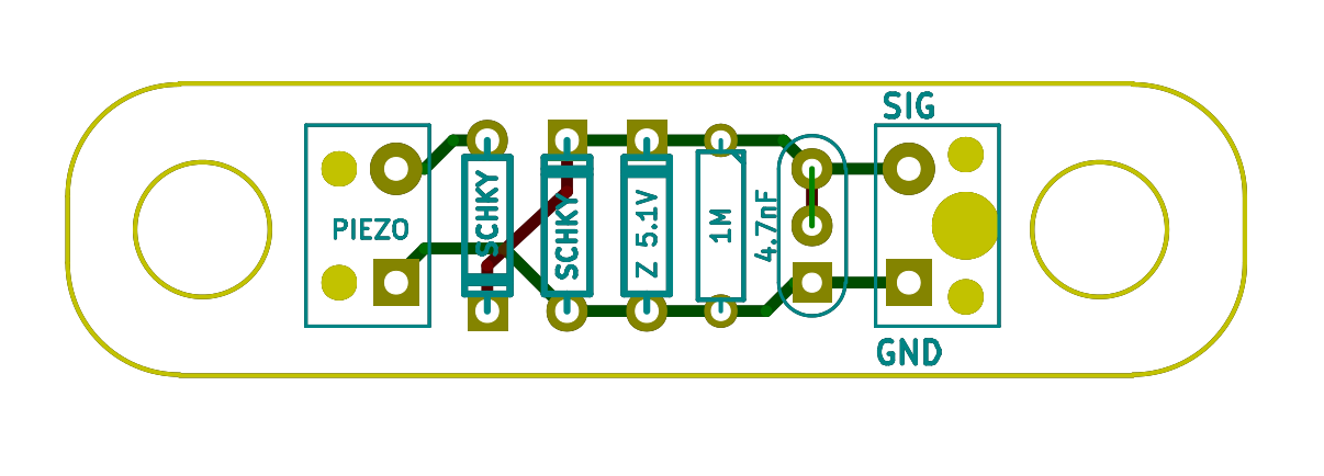
We actually used this imput directly into the 16 analog inputs of an Arduino Mega for the first version of the foam dart range — although that did require speeding up the analog to digital converter to it’s maximum rate to be able to scan all 16 inputs every 10ms. The code then looked for the signal going above a certain threshold, and counting a hit if it hadn’t already done so within the last 10ms.

This all worked fine for most of the installations, but we were continually re-tuning the threshold level for reliability. For the second version we added a FET buffer on the receiving board, so the signal would be digitally triggered once the voltage reached the on-voltage of the FET (around 0.7V) and fed that into an interrupt pin on the Arduino. As we’d changed to having a controller on each target to run the LED display, and report hits via radio back to the main controller, changing to an interrupt means we always read hits over the impact threshold.

The FET buffer gives a clear logic low when the sensor pulse goes above 0.7V, which returns to logic high when the sensor pulse drops below 0.7V. And because of this threshold, coupled with the size of the capacitor, it will only trigger from a sharp pulse of a high enough energy. If you hit this sensor with a dart (or flick it very hard with your finger) it will trigger reliably, but if pressed or pushed, the voltage in the capacitor doesn’t reach the trigger threshold, and no signal is passed.
The other change for installation that we did make was to add a single M6 nut glued to the back plate of the piezo. While it does work without, the additional mass across the piezo causes larger deflections in it, giving more energy to the signal and increasing the reliability of the input.